| | |
 | Gut zu wissen: Hilfreiche Tipps und Tricks aus der Praxis prägnant, und auf den Punkt gebracht für CATIA & Co. |
| | |
 | Skalierbare und leistungsstarke Enterprise Visualisierungslösung für die Fertigungsindustrie, eine Pressemitteilung
|
|
Autor
|
Thema: 1D-3D-Verbindung (2947 mal gelesen)
|
amigician
Mitglied
Berechnungsingenieur

   Beiträge: 176
Registriert: 18.06.2004 P4 3.6Ghz 2GB RAM
WinXP SP2
Autodesk Inventor 11 Series SP3
Ansys DesignSpace 11.0 SP1
|

 erstellt am: 26. Mai. 2005 10:12
  <-- editieren / zitieren --> <-- editieren / zitieren -->   Unities abgeben: Unities abgeben:          
|
amigician
Mitglied
Berechnungsingenieur
Beiträge: 176
Registriert: 18.06.2004 P4 3.6Ghz 2GB RAM
WinXP SP2
Autodesk Inventor 11 Series SP3
Ansys DesignSpace 11.0 SP1
|
 erstellt am: 27. Mai. 2005 10:42 <-- editieren / zitieren --> Unities abgeben:
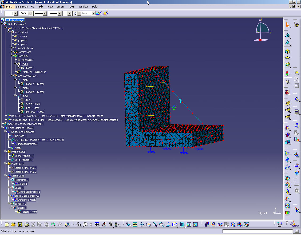
Hallo nochmal Füge hier mal noch ein Bild eines Beispiels bei, damit ihr euch das besser vorstellen könnt: Es ist ein Winkel, in dem zusätzlich ein Seil gespannt wird. Die Knoten von Seil(1D-Beam-Elemente) liegen auf Knoten der Winkel(3D-Oktaeder-Elemente). Jetzt muss da noch irgend eine Verbindung rein, damit das Seil nicht davon fliegt. Gruss
Lorenz Eine Antwort auf diesen Beitrag verfassen (mit Zitat/Zitat des Beitrags) IP |
ij
Mitglied
Konsultant
Beiträge: 7
Registriert: 01.05.2005
|
erstellt am: 31. Mai. 2005 08:21 <-- editieren / zitieren --> Unities abgeben: Nur für amigician 
|
stundenblume
Mitglied
Beiträge: 9
Registriert: 13.03.2007
|
erstellt am: 29. Feb. 2008 11:36 <-- editieren / zitieren --> Unities abgeben: Nur für amigician
Hallo, das schöne an einem Forum ist dass die Lösungen noch Jahre nachzulesen sind. Allerdings nicht wenn man sie in PMs beantwortet werden.
Mich würde die Lösung auch interessieren.
Gruß
Sebastian Eine Antwort auf diesen Beitrag verfassen (mit Zitat/Zitat des Beitrags) IP |
amigician
Mitglied
Berechnungsingenieur
Beiträge: 176
Registriert: 18.06.2004 P4 3.6Ghz 2GB RAM
WinXP SP2
Autodesk Inventor 11 Series SP3
Ansys DesignSpace 11.0 SP1
|
erstellt am: 29. Feb. 2008 14:19 <-- editieren / zitieren --> Unities abgeben:
Hello Lorenz I'm glad to help you. You can post this to the board. The selection of points is really a bit tricky. It is necessary to be attentive during selecting elements for the first connecting set and for the second. Because there is possible a multiple selection. I also had some problems at the first time.
And also you need a real elements on 3D model (points, lines or faces) to make a connection. Here is a link with a discussion how to separate an area on the 3D model. This can be useful not only for connections but also for boundary conditions and forces. http://ww3.cad.de/foren/ubb/Forum395/HTML/000069.shtml Surface mesh is also possible way but I think it is more difficult for most applications. And also as I remember this requires Advanced Meshing Tools license. Regards Igor ----- Original Message -----
Dear Igor Thank you for your answer. I tried it in a similiar way first. But wasn't quite sure whether the bodies have to be in different parts or not. Also had problems with selection of end points.
A specialist from IBM Germany has described a different approach to me. He used a Surface Mesh, connected the the beam-elements by automatic mesh capturing and fille the surface with the tetrahedron filler. Regards, Lorenz P.S. Is it o.k. if I post parts of this to the board?
Eine Antwort auf diesen Beitrag verfassen (mit Zitat/Zitat des Beitrags) IP |
amigician
Mitglied
Berechnungsingenieur
Beiträge: 176
Registriert: 18.06.2004 P4 3.6Ghz 2GB RAM
WinXP SP2
Autodesk Inventor 11 Series SP3
Ansys DesignSpace 11.0 SP1
|
erstellt am: 29. Feb. 2008 14:21 <-- editieren / zitieren --> Unities abgeben:
Dear Lorenz There are two possible ways to model your analysis. The first one by using 1D elements like on your model. But for this you need Generative Assembly Structural Analysis (GAS) license. Using GAS product you should make two General Analysis Connections (please see Analysis Connections chapter in documentation) between end points of 1D element and appropriate elements on the 3D model (line, face or point). But point it is not very good connection for 3D model. Using point connection you will get too high stresses level around it and this is not realistic. It is better to make more realistic connection elements on the 3D model. When the General Analysis Connections are created you should add Smooth or Rigid connections using Analysis Connections as supports. The second way don't need a 1D elements at all. You can make a Rigid Spring Virtual Part between two fases on the 3D model. But you need to calculate shtifness of your steel beam element like for spring and add this value as a shtifness for Rigid Spring Virtual Part. Also you need to make a new axis system with X axis along beam element. And use this coordinate system for Rigid Spring Virtual Part. If you will send me your e-mail adress on igor@3d-point.net I will send you an examples to this case. Igor
----- Original Message -----
Dear Igor
I see on your Website http://3d-point.net that you have used some 1D-3D-Connection in Chair_frame_analysis.jpg. I am trying to do something simular, but can't find out how to do it. Please have a look a my thread: http://ww3.cad.de/foren/ubb/Forum395/HTML/000089.shtml
Can you help my? Thanks, Lorenz
[Diese Nachricht wurde von amigician am 29. Feb. 2008 editiert.] Eine Antwort auf diesen Beitrag verfassen (mit Zitat/Zitat des Beitrags) IP |
GEOP
Mitglied
Student
Beiträge: 24
Registriert: 26.05.2009
|
erstellt am: 26. Mai. 2009 14:27 <-- editieren / zitieren --> Unities abgeben: Nur für amigician
|
dizubi
Mitglied
Konstrukteur
Beiträge: 7
Registriert: 25.05.2009
|
erstellt am: 26. Mai. 2009 22:53 <-- editieren / zitieren --> Unities abgeben: Nur für amigician
|
GEOP
Mitglied
Student
Beiträge: 24
Registriert: 26.05.2009
|
erstellt am: 28. Mai. 2009 19:34 <-- editieren / zitieren --> Unities abgeben: Nur für amigician
Hallo dizubi! Danke für die Antwort Ich finds trotzdem nicht. Kann es sein, dass das irgendwie mit der (evtl. nicht passenden) Lizenz zu tun hat. Ich habe die Umgebung "Advanced Meshing Tools" zur Verfügung aber ich finde weder "Advanced Surface Mesher" noch die Toolbar "Local Specifications" noch "Add/Remove Constraints". Bin ich zu blöd, ist es versteckt, gibt es einen Trick, wie man es finden? Oder kann es tatsächlich sein, dass es es in meiner Version einfach nicht gibt? Gruß GEOP
[Diese Nachricht wurde von GEOP am 28. Mai. 2009 editiert.] Eine Antwort auf diesen Beitrag verfassen (mit Zitat/Zitat des Beitrags) IP |
Landskronbier
Mitglied
Dipl.-Ing. in Fahrzeugkonstruktion
Beiträge: 271
Registriert: 27.07.2004 CATIA V5, Siemens NX
|
erstellt am: 05. Jun. 2009 16:37 <-- editieren / zitieren --> Unities abgeben: Nur für amigician
Hallo Geop, du muss in der Umgebung "Advanced Meshing Tools" zunächst den Surface Mesher starten. Danach kommst du automatisch in der Surface Mesher Umgebung und dort findest du die Toolbar geometrical specification in der du deine suchende Funktion finden wirst. ------------------
MfG Martin
maba-engineering
 Eine Antwort auf diesen Beitrag verfassen (mit Zitat/Zitat des Beitrags) IP |

 Foren auf CAD.de


 |
|