Hallo zusammen,
ich versuche mich gerade an der Rissmodellierung mit Federn. An einem kleinen Modell will ich mit Hilfe von Fastener und Connector in Abhängigkeit der Verschiebung die entsprechenden Kräfte in der festgelegten Rissebene aufbringen.
Ich bin mir jedoch bei der Vorgehensweise unsicher.
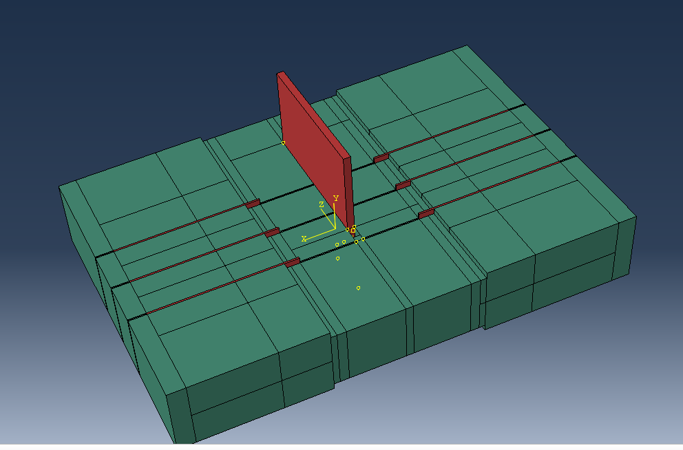
1) Ich habe die beiden Parts erstellt und dann unter Special -> Fasteners -> Points offset from edges auf einer der Oberfläche die Haltepunkte erstellt
2) dann unter Special -> Fasteners -> Lines by projecting points die Quell- und Zieloberfläche angegeben
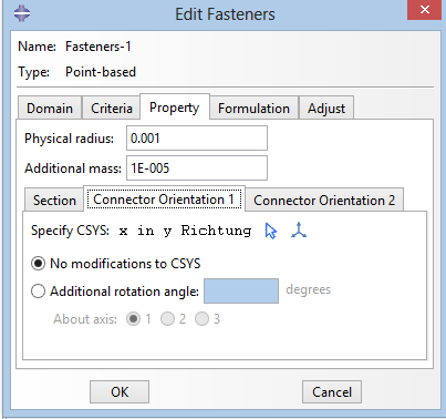
3) Create Fasteners -> Point-based und dann das zuvor erstellte Set ausgewählt
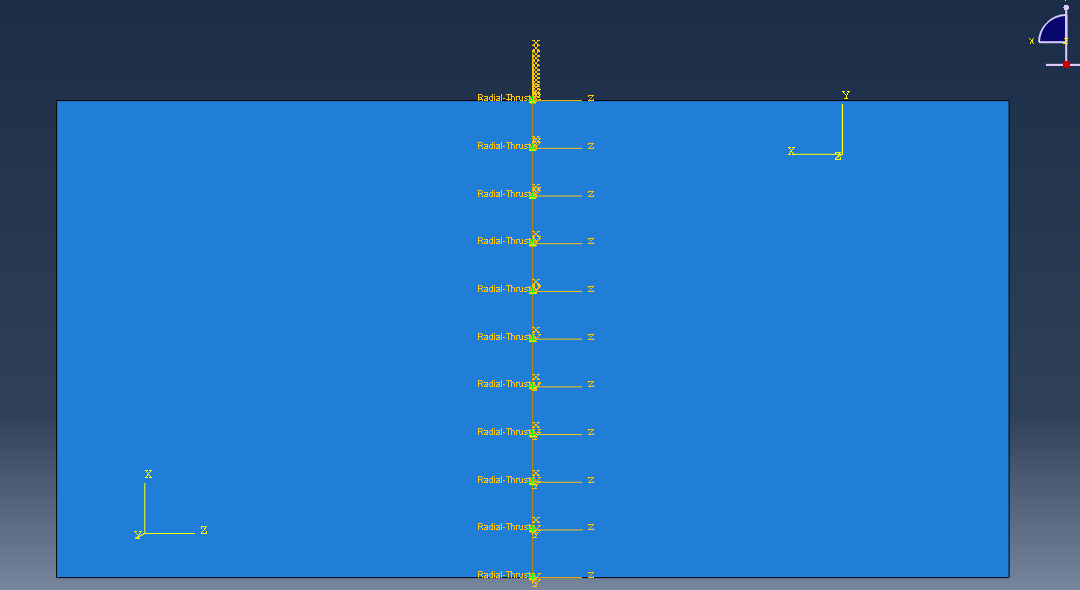
4) Create Connector Section Translation: Radial-Thrust Rotational: None
5) Create Connector Assignment die Attachment lines ausgewählt und das Koordinatensystem entsprechend angepasst
Als Warnungen erhalte ich:
Zitat:
The nodes of a connector element 190 (assembly) type radial-thrust are coincident. This may lead to convergence problems in the increments when this radius remains zero or small since the direction between the two nodes in the radial plane is indeterminate. Please consider placing the connector nodes such that the distance between them in the radial plane is nonzero.
und Abgebrochen wird durch:
Zitat:
The deformable element nodes contained in node set ErrNodeSpaNodeNoMass-Step1 have no mass associated with them and some translational degrees of freedom at the nodes are not constrained. Either mass must be definedor all of the translational degrees of freedom must be constrained.
Für jede Hilfe bin ich dankbar!
Eine Antwort auf diesen Beitrag verfassen (mit Zitat/Zitat des Beitrags) IP

 Foren auf CAD.de


 |
|