Hallo Kollabierer.
Willkommen im Forum.
1.) Nachfolgend ein Auszug aus der internen FlowSimulation-KnowledgeBase
hinsichtlich Kavitation
2.) Beispiele
- Am Ende des Artikels wird auf das Beispiel im Handbuch
verwiesen.
Handbuch als PDF und Beispieldateien sollten bei einer Standard-
Installation auf Deiner Festplatte installiert worden sein
- Bei den "Standard-Examples" gibt es auch das "Ball-Valve-Example"
(gleich als erstes Beispiel).
Dort könnte man z.B. die Kugel bis auf einen sehr geringen
Spalt schließen, einen hohen Eingangsdruck und einen hohen
outlet-volume-flow jeweils für Wasser angeben.
Das drüfte früher oder später auch zu Kavitation führen.
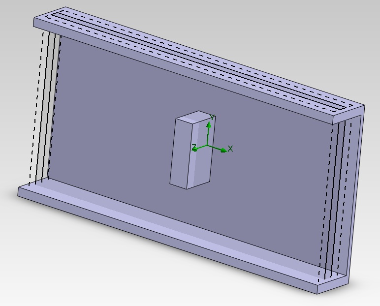
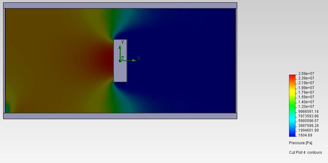
3.) Darstellung
Wie häufig bei Flow-Problemen sind Verteilung von Druck und
Geschwindigkeiten am interessantesten.
Man arbeitet bei der Darstellung mit den Flow-Trajectories,
ISO-Planes oder evtl. auf 2D-cut-plots.
So eine generelle Regel gibt es nicht ...
4.) Hier nun der Auszug aus der Knowledgebase:
Article ID: x278
Applies to: SolidWorks Flow Simulation
Version: All Versions
Category: Fluid Mechanics
Created: 11/28/2005
Last Revised: 04/26/2010
Discussion
Definition
Cavitation occurs when vapor is formed at points along the flow field at which the local pressure falls below the saturation pressure; local boiling takes place without the addition of heat. Low static pressure regions will occur at points where high local velocities are encountered. The small bubbles formed in the region of low pressure collapse as they enter regions of higher pressure further downstream. This repeated collapses near the surface of the blades can cause damage to the blade surface. Cavitation can also occur in other liquid flow machinery as pumps and turbines, and valves and other flow devices.
Source: Introduction to Fluid Mechanics by James E.A. John and William L. Haberman.
Cavitation up to version 2006
The program can not directly simulate cavitation. Nevertheless, local areas of negative pressure may indicate the presence of cavitation.
Cavitation with version 2007 to 2009
SolidWorks Flow Simulation can still not directly simulate cavitation, but a new option was implemented to estimate the occurrence of cavitation in Water.
The best visualization parameter to use to evaluate the likeliness of cavitation is Dissolved gas mass fraction. It represents the mass fraction of air dissolved in water.
Please refer to the program's online documentation:
Cavitation chapter page 1-27 (33 of 162) of the technicalreference.pdf in [Installation folder]\lang\english\Docs.
The Cavitation topic of the SolidWorks Flow Simulation 2007 Online Help was copied below for your convenience).
Cavitation starting with version 2010
SolidWorks Flow Simulation can estimate the occurrence of cavitation in industrial liquids such as fuel, oils. Cavitation becomes important in a high pressure systems such as fuel injectors used in Aerospace and Automotive industries. The model requires minimum data to be provided from the user that makes it easier to apply.
The following models of cavitation are available in Flow Simulation:
Engineering cavitation model (for pre-defined water only, as in previous versions):
This model employs a homogeneous equilibrium approach and is available for pre-defined water only. It has the capability to account for the thermal effects. The fluid is assumed to be a homogeneous gas-liquid mixture with the gaseous phase consisting of the vapour and non-condensable (dissolved) gas. The vapour mass fraction is defined at the local equilibrium thermodynamic conditions. The dissolved gas mass fraction is a constant, which can be modified by user.
Isothermal cavitation model (new model in version 2010 for any user-defined incompressible liquid):
This model is based on the approach considering isothermal two-phase flows. Fluid density is defined by the barotropic equation of state. The Isothermal cavitation model can be employed for any user-defined incompressible Liquid in the Engineering Database by selecting the Cavitation effect check box and specifying the Molar mass of the liquid and the Saturation pressure at the specific Temperature.
--------------------------------------------------------------------------------
From SolidWorks Flow Simulation 2010 "Solving Engineering Problems":
Cavitation is a common problem for many engineering devices in which the fluid is in liquid state. The deleterious effects of cavitation include: lowered performance, load asymmetry, erosion and pitting of blade surfaces, vibration and noise, and reduction of the overall machine life. However, cavitation is also used in some industrial processes, such as the fuel spray formation in diesel and gasoline engines.
Recommendations
If you analyze a flow of water in some points of which the local static pressure can reach the saturation pressure at the local temperature causing cavitation or if a vaporization of water can occur in the water flow due to intense heating, it is recommended to use the Engineering cavitation model.
Cavitation area growths slowly during calculation and there is a risk that the calculation will stop before the cavitation area develops completely. To avoid this, specify Global Goal of Average Density and increase the Analysis interval on the Finish tab of the Calculation Control Options dialog box. Also make sure that the other finish conditions do not cause the calculation to stop before goals are converged. The easiest way to ensure this is to select If all are satisfied in the Value cell for the Finish conditions on the Finish tab of the Calculation Control Options dialog box.
The Cavitation option is not applicable if you calculate a flow in the model without flow openings (inlet and outlet).
The fluid region where cavitation occurs must be well resolved by the computational mesh.
Besides the Volume Fraction of Vapour you can also select Density as the visualization parameter to see the cavitation areas in your simulation.
Limitations and Assumptions for Engineering cavitation model
The properties of the dissolved non-condensable gas are set to be equal to those of air. By default, the mass fraction of the dissolved non-condensable gas is set to 10-5, but it can be modified by the user in the range of 10-4...10-8.
The temperature and pressure ranges in the cavitation area must be within the following bounds:
277.15 < T < 583.15 K, 800 < P < 107 Pa.
The velocities and temperatures of the gaseous (including vapour and non-condensable gas) and liquid phases are assumed to be the same.
The model does not describe the detailed structure of the cavitation area, i.e parameters of individual vapour bubbles are not considered.
For mixtures of different liquids the cavitation option cannot be selected.
The volume fraction of vapour is limited by 0.9. The parameters of the flow at the inlet boundary conditions must satisfy this requirement.
Limitations and Assumptions for Isothermal cavitation model
The fluid temperature is constant and the thermal effects are not considered.
The fluid density is defined by the barotropic equation of state.
The liquid phase is an incompressible fluid.
When liquid turns into vapour completely the vapour and non-condensable gas density is defined by the ideal gas law.
The fluid contains non-condensable (dissolved) gas. One of the four gases can be used as dissolved gas: Air, Carbon dioxide, Helium and Methane. By default, the non-condensable gas is Air and the mass fraction is set to 10-4. This is a typical model value appropriated in most cases but it can be modified by the user in the range of 10-2...10-6..
--------------------------------------------------------------------------------
Cavitation validation example
There is a cavitation validation automatically installed with the software.
Please go to the following directory:
[Installation folder]\Validation Examples\22 - Cavitation on a hydrofoil
The write up for this validation is on page 153 of 162 in technicalreference.pdf .
The following web sites may also be helpful.
Wikipedia: http://en.wikipedia.org/wiki/Cavitation
Physics Today on the Web: http://www.aip.org/pt/feb00/maris.htm
-----------------
Gutes Gelingen
Roland 
------------------
Das Unmögliche möglich zu machen
ist ein Ding der Unmöglichkeit.
Andy Brehme - deutscher Fussballer
Eine Antwort auf diesen Beitrag verfassen (mit Zitat/Zitat des Beitrags) IP

 Foren auf CAD.de