| | |  | Gut zu wissen: Hilfreiche Tipps und Tricks aus der Praxis prägnant, und auf den Punkt gebracht für Ansys | | | |  | Ansys 2026 R1 Update und Praxis-Tipps - Fokus Optimale Trainingsdaten für KI mit optiSLang, ein Webinar am 20.05.2026
|
|
Autor
|
Thema: Ausrichtung Solids (7068 mal gelesen)
|
Jens.Friedrich
Moderator
Dipl. -Ing.
   
   Beiträge: 1051
Registriert: 09.09.2005 ANSYS2021 R2
|

 erstellt am: 08. Mai. 2007 13:01
  <-- editieren / zitieren --> <-- editieren / zitieren -->   Unities abgeben: Unities abgeben:          
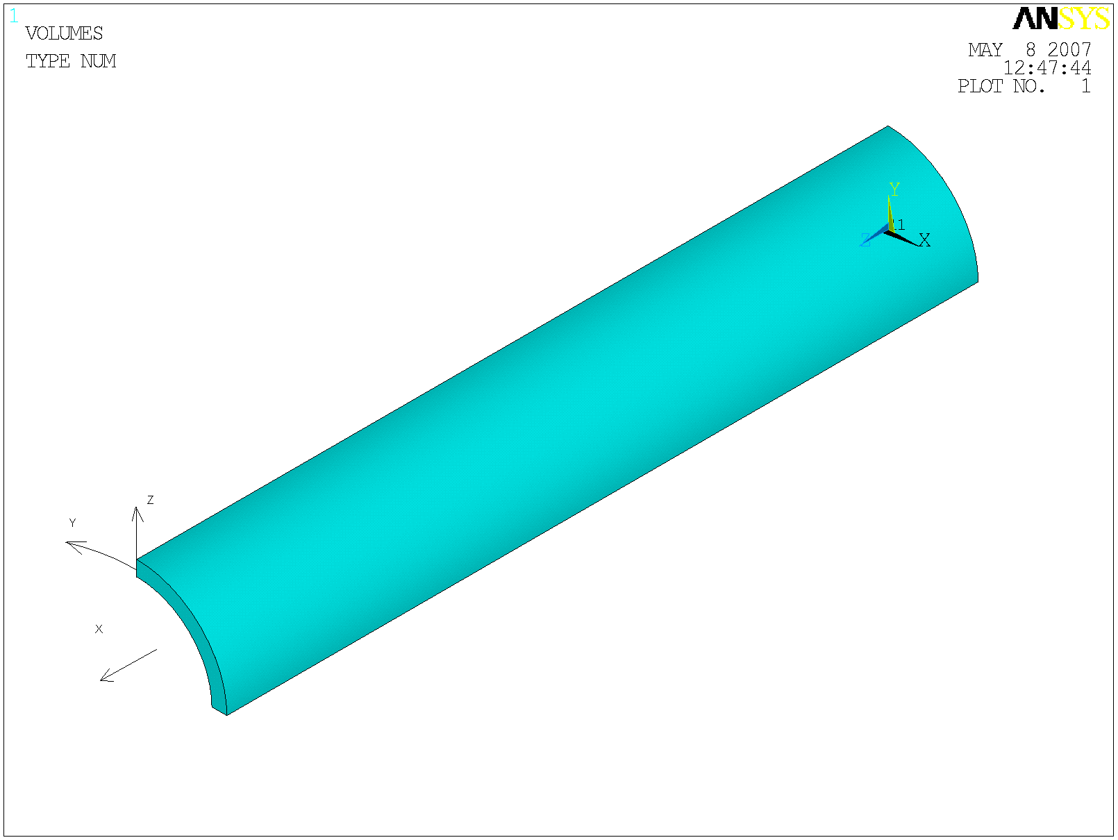
Hallo Leute, ich hab mal wieder ein Problem mit der Ausrichtung von Elementen in ANSYS. Ich hätte gern eine Ausrichtung wie im angehangenen Bild. Dafür benötige ich ein lokales (ESYS arbeitet nur mit lokalen KS) zylindrisches KS mit R=Z PHI=Y und Z=X
Leider kann ich kein locales ks auf basis von csys,5 oder csys,6 erstellen, was diesem Fall meines erachtens entspricht. wäre dies möglich könnte ich die elemente einfach per emod,,esys ausrichten.
vielleicht hat ja jemand eine idee wie ich solch ein ks erzeuge. Eine Möglichkeit es den Befehl VEORIENT zu verwenden, welcher jedoch nicht mit VSWEEP funktioniert. Schade. Wer kennt die Lösung? hier der verwendete input:
fini
/clear
/prep7 R_I=10
R_A=12
LAE=100
csys,0
cyl4,0,0,R_I,0,R_A,90,LAE
et,1,185
vsweep,1
/view,1,1,1,1
/PSYMB,ESYS,1
eplot
/wait,2
local,11,1
emod,all,esys,11
eplot gruß
jens
/wait,100 ------------------
Jens Friedrich
Institut für Leichtbau und Kunststofftechnik
TU-Dresden [Diese Nachricht wurde von Jens.Friedrich am 08. Mai. 2007 editiert.] Eine Antwort auf diesen Beitrag verfassen (mit Zitat/Zitat des Beitrags) IP |
serg1976
Mitglied
mathphysicist - researcher

Beiträge: 50
Registriert: 03.05.2007
|
erstellt am: 08. Mai. 2007 15:54 <-- editieren / zitieren --> Unities abgeben: Nur für Jens.Friedrich 
The changing of coordinate system (solid185) has sense only for the: -orthotropic materials; -border (initial) DOF conditions; For the second one it is more convenient to use CE command. Write, what is the goal, possible I’ll say you more comprehensive answer. Regards Serge. Eine Antwort auf diesen Beitrag verfassen (mit Zitat/Zitat des Beitrags) IP |
Jens.Friedrich
Moderator
Dipl. -Ing.
Beiträge: 1051
Registriert: 09.09.2005 ANSYS2021 R2
|
erstellt am: 08. Mai. 2007 16:14 <-- editieren / zitieren --> Unities abgeben:
I want to use the element coordinate system for orthotropic materials. solid185 is only an example. i want to use layered solids to model thickwalled composite strctures. those elements must be proper orientated! one can use VEORIENT, but its not valid with sweeping! maybe you know a possibility to create a local coordinate system with the proper orientation (like csys,5 and csys,6) sorry for my poor english
jens ------------------
Jens Friedrich
Institut für Leichtbau und Kunststofftechnik
TU-Dresden Eine Antwort auf diesen Beitrag verfassen (mit Zitat/Zitat des Beitrags) IP |
serg1976
Mitglied
mathphysicist - researcher
Beiträge: 50
Registriert: 03.05.2007
|
erstellt am: 08. Mai. 2007 17:02 <-- editieren / zitieren --> Unities abgeben: Nur für Jens.Friedrich
Of course it is nod valid, as sweep also sweep the orientation! For the case orthotropic, layered model: All SOLID46 and SOLID191 3-D layered solid elements, SOLID95 elements with KEYOPT(1) = 1, SOLID186 Layered Solid, and SOLSH190 solid shell elements in the selected set are considered for reorientation (EORIENT command). Thus, you mistake is using solid185, use aforesaid elements! Eine Antwort auf diesen Beitrag verfassen (mit Zitat/Zitat des Beitrags) IP |
horval
Mitglied
Verfahrenstechniker
Beiträge: 242
Registriert: 19.04.2003 Intel P4 2.8GHz, PNY_Quadro 980 XGL
3Gb RAM,WIN XP Pro SP2
|
erstellt am: 08. Mai. 2007 19:23 <-- editieren / zitieren --> Unities abgeben: Nur für Jens.Friedrich
Zitat:
Original erstellt von Jens.Friedrich:
Ich hätte gern eine Ausrichtung wie im angehangenen Bild.
don`t worry, here it is fini
/clear
/prep7 R_I=10
R_A=12
LAE=100
csys,0
cyl4,0,0,R_I,0,R_A,90,LAE
et,1,185
CSYS,5
VGEN, ,1, , , ,90, , , ,1
vsweep,1
VGEN, ,1, , , ,-90, , , ,1
/view,1,1,1,1
/PSYMB,ESYS,1
CSYS,0
eplot
 ------------------
 Eine Antwort auf diesen Beitrag verfassen (mit Zitat/Zitat des Beitrags) IP |
serg1976
Mitglied
mathphysicist - researcher
Beiträge: 50
Registriert: 03.05.2007
|
erstellt am: 08. Mai. 2007 19:50 <-- editieren / zitieren --> Unities abgeben: Nur für Jens.Friedrich
|
horval
Mitglied
Verfahrenstechniker
Beiträge: 242
Registriert: 19.04.2003 Intel P4 2.8GHz, PNY_Quadro 980 XGL
3Gb RAM,WIN XP Pro SP2
|
erstellt am: 08. Mai. 2007 21:07 <-- editieren / zitieren --> Unities abgeben: Nur für Jens.Friedrich
Zitat:
Original erstellt von serg1976:
I'm not understand why are you happy!?
1. You don`t have to understand.
2. I did not say that I`m happy. Zitat:
Original erstellt von serg1976:
Try to use more complex geometry and you'll see that it will be problems.
3. We talk about Jens` input and not about a complex geometry!
4. How can you say what I will see! ------------------
Eine Antwort auf diesen Beitrag verfassen (mit Zitat/Zitat des Beitrags) IP |
Jens.Friedrich
Moderator
Dipl. -Ing.
Beiträge: 1051
Registriert: 09.09.2005 ANSYS2021 R2
|
erstellt am: 09. Mai. 2007 09:19 <-- editieren / zitieren --> Unities abgeben:
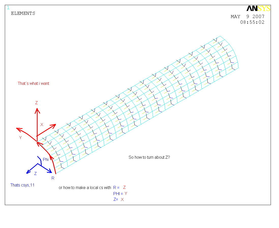
@horval: I want the orientation like in the pic on the end left bottom. @serg1976: I know about the EORIENT and that I can use ist only with layered solids or solsh. But it´s useable only for solids. So what can I do when i want to use shells. the problem keeps nearly the same but what can you use now? like in the following example: (Please see the attachment for explanation) fini
/clear
/prep7 R_I=10
R_A=0
LAE=100
csys,0
cyl4,0,0,R_I,0,R_A,90,LAE
vdele,all,0
et,1,181
csys,1
asel,s,loc,x,R_I
asel,invert
adele,all
alls
amesh,all
/view,1,1,1,1
/dev,vector,on
/PSYMB,ESYS,1
eplot !NOW I Want the orientation to be turned around the z !axes
/wait,2
local,11,1
emodif,all,esys,11
eplot !If there is a possibility to make an cyl local cs !with R=Z Phi=Y amd Z=X everything would be perfect ------------------
Jens Friedrich
Institut für Leichtbau und Kunststofftechnik
TU-Dresden [Diese Nachricht wurde von Jens.Friedrich am 09. Mai. 2007 editiert.] Eine Antwort auf diesen Beitrag verfassen (mit Zitat/Zitat des Beitrags) IP |
Jens.Friedrich
Moderator
Dipl. -Ing.
Beiträge: 1051
Registriert: 09.09.2005 ANSYS2021 R2
|
erstellt am: 09. Mai. 2007 10:36 <-- editieren / zitieren --> Unities abgeben:
@all: another problem of eorient is that you can orient the normal but not rotate about it. see the following input: fini
/clear
/prep7 R_I=10 R_A=12
LAE=100
csys,0
cyl4,0,0,R_I,0,R_A,90,LAE
et,1,190
vsweep,1
/dev,vector,on
/PSYMB,ESYS,1
eplot
/anno,dele
/ANUM ,0, 1, 1.2303, -.74699
/TSPEC, 15, .600, 1, 0, 0
/TLAB, 1.0, -.80,Z = -Z
/TLAB, 1.0, -.85,Now Eorient would be fine
/TLAB, 1.0, -.90,but its not possible
/wait,5
*ask,input,Weiter
eorient,,negz,90 /anno,dele
/TLAB, 1.0, -.80,Now why its turned,if its ignored?
eplot
/wait,5
*ask,input,Weiter
!Do a replot by clicking, to see the difference
/anno,dele
/TLAB, 1.0, -.80,Well lets try local cs
local,11,1
emod,all,esys,11
eplot
/TLAB, 1.0, -.85,now i can orientat the normal Z=x
*ask,input,Weiter /anno,dele
/TLAB, 1.0, -.80,Normal is right
/TLAB, 1.0, -.85,but what can i do with the x axis?
/TLAB, 1.0, -.90,I need an rotation about Z
eorient,all,negx,90
/rep Well I can do an internal roation about 90 deg in the section input... not very fine solution ------------------
Jens Friedrich
Institut für Leichtbau und Kunststofftechnik
TU-Dresden [Diese Nachricht wurde von Jens.Friedrich am 09. Mai. 2007 editiert.] Eine Antwort auf diesen Beitrag verfassen (mit Zitat/Zitat des Beitrags) IP |
Zapfonator
Mitglied
Ingenieur
Beiträge: 115
Registriert: 31.07.2003
|
erstellt am: 09. Mai. 2007 11:26 <-- editieren / zitieren --> Unities abgeben: Nur für Jens.Friedrich
Hallo Jens, Kurz mal OFF-Topic: Ich seh gerade, dass Du viel mit Layered Solid 186 rechnest. Hast Du schon die Ansys 11 Version ? Lass doch mal ein älteres Modell (Ansys 10, Solid 186 mit eingebauten Lagen-Winkel-Orientierungen über Sections) nochmal mit der 11er durchlaufen und vergleiche mal die Ergebnisse. Bemerkst Du dabei etwas ? ------------------
----------------------------------
Mit Humor geht alles besser....... Eine Antwort auf diesen Beitrag verfassen (mit Zitat/Zitat des Beitrags) IP |
serg1976
Mitglied
mathphysicist - researcher
Beiträge: 50
Registriert: 03.05.2007
|
erstellt am: 10. Mai. 2007 14:22 <-- editieren / zitieren --> Unities abgeben: Nur für Jens.Friedrich
I’d like only to note that it is more convenient for orthotropic properties to use the elements with possibility to change its coordinate system. Of course, the element orientations are determined by element coordinate system. However, for instance by the free meshing or sweeping the element’s normal sometimes is not determined (mixed) + or -. Thus, I insistently advise to use the elements with the possibility to change cs, for instance using EORIENT. From another side for the multilayer shell elements the (+/-) don’t have the sense thus the orientation cs is identically determined by element coordinate system. Eine Antwort auf diesen Beitrag verfassen (mit Zitat/Zitat des Beitrags) IP |
Jens.Friedrich
Moderator
Dipl. -Ing.
Beiträge: 1051
Registriert: 09.09.2005 ANSYS2021 R2
|
erstellt am: 10. Mai. 2007 17:01 <-- editieren / zitieren --> Unities abgeben:
@all: thanks for helping me! @serg: I know about that in I-DEAS and ABAQUS you can do the thing i want very easy. In ABAQUS for instance you can do a "extra rotation" about the normal. So you can tell the elements to take the pos R axis as normal (Z) and than ABAQUS is asking for another in-plane rotation (X/Y is than proper). In Ideas it´s even more easy: The programm is asking for the X Y and Z axis and you can use every cs with every axis. It´s possible to orient along a surface and the rotate inplane. I can´t believe that noone had this problem before in ANSYS. For me its something very basic to modell composites. In ANSYS I can´t do that, even though I have ESYS, EORIENT, VEORIENT (like discribed in the last example) Thank you for advice and maybe you can find a way to orient the bricks properly Gruß
Jens ------------------
Jens Friedrich
Institut für Leichtbau und Kunststofftechnik
TU-Dresden Eine Antwort auf diesen Beitrag verfassen (mit Zitat/Zitat des Beitrags) IP |
serg1976
Mitglied
mathphysicist - researcher
Beiträge: 50
Registriert: 03.05.2007
|
erstellt am: 10. Mai. 2007 17:31 <-- editieren / zitieren --> Unities abgeben: Nur für Jens.Friedrich
|
Jens.Friedrich
Moderator
Dipl. -Ing.
Beiträge: 1051
Registriert: 09.09.2005 ANSYS2021 R2
|
erstellt am: 11. Mai. 2007 09:37 <-- editieren / zitieren --> Unities abgeben:
Hallo Serg! maybe you can help me with the attached input! I don´t understand how to orient the elements porperly. Thank you very much for advice Jens ------------------
Jens Friedrich
Institut für Leichtbau und Kunststofftechnik
TU-Dresden Eine Antwort auf diesen Beitrag verfassen (mit Zitat/Zitat des Beitrags) IP |
serg1976
Mitglied
mathphysicist - researcher
Beiträge: 50
Registriert: 03.05.2007
|
erstellt am: 11. Mai. 2007 15:14 <-- editieren / zitieren --> Unities abgeben: Nur für Jens.Friedrich
There is some problems with visualization of element CSs, thus it is more demonstrably and reliable to consider (compose) whole simple task with anisotropic material. Description: there is an double layered beam with anisotropic properties; in particular X Young's modulus is in 100 times bigger then in Y and Z directions.
1) Consider with f,17,fx,-1e3 and PLNSOL, U,X, 0,1.0
2) Consider with f,17,fy,-1e3 and PLNSOL, U,Y, 0,1.0
Thus you’ll see the difference in the deflection
3) Add: local,11,0,,,,90 and emod,all,esys,11
You’ll get vice versa results, what were expected!
Thus, the Element CS orientation could be changed! /NOPR ! Suppress printing of UNDO process
/PMACRO ! Echo following commands to log
FINISH ! Make sure we are at BEGIN level
/CLEAR,NOSTART ! Clear model since no SAVE found
! WE SUGGEST YOU REMOVE THIS LINE AND THE FOLLOWING STARTUP LINES
/input,start100,ans,'D:\Program Files\Ansys Inc\v100\ANSYS\apdl\',,,,,,,,,,,,,,,,1
/PREP7
smrt,off
ANTYPE,STATIC ! STATIC ANALYSIS
NLGEOM,ON ! LARGE DEFLECTION OPTION
LUMPM,ON
ET,1,SOLID46 ! ANISOTROPIC SOLID
R,1,2
RMORE
RMORE,1,0,.25
MP,EX,1,1E4 ! LABELED MATERIAL PROPERTY INPUT
MP,EY,1,1E6
MP,EZ,1,1E6
MP,NUXY,1,.3
MP,NUYZ,1,.3
MP,NUXZ,1,.3
MP,GXY,1,1E6
MP,GYZ,1,1E6
MP,GXZ,1,1E6
BLOCK,0,1,0,1,0,5,
TYPE,1
MAT,1
real,1
!MSHA,1,3D ! USING TETS is mistakable
ESIZE,0.5
VMESH,1 ! conductor
!local,11,0,,,,90
!emod,all,esys,11 !rotation of nodal CS round Z on 90 degres.
nsel,s,loc,z,0
d,all,all,
nsel,all
f,17,fx,-1e3
!f,12,fy,-1e3
!
FINISH
/SOLU
AUTOTS,ON ! USE AUTOMATIC LOAD STEPPING
NSUBST,100 ! START WITH MAX OF 10 SUBSTEPS FOR EACH LOAD STEP
LNSRCH,ON ! USE LINE SEARCH METHOD
OUTPR,BASIC,LAST ! BASIC PRINTOUT IN THE LAST SUBSTEP
OUTRES,ALL,all
SOLVE
FINISH
!*
/POST1
!*
/EFACET,1
PLNSOL, U,X, 0,1.0
!*
)/GOP ! Resume printing after UNDO process
)! We suggest a save at this point
Eine Antwort auf diesen Beitrag verfassen (mit Zitat/Zitat des Beitrags) IP |
ife
Mitglied
Berechnungsdienstleister FEM
Beiträge: 1397
Registriert: 29.10.2002 IFE Deutschland
Simulation ANSYS
Workbench MAPDL Multiphysics CFX
|
erstellt am: 11. Mai. 2007 15:52 <-- editieren / zitieren --> Unities abgeben: Nur für Jens.Friedrich
|
serg1976
Mitglied
mathphysicist - researcher
Beiträge: 50
Registriert: 03.05.2007
|
erstellt am: 11. Mai. 2007 16:03 <-- editieren / zitieren --> Unities abgeben: Nur für Jens.Friedrich
|
Die-mit-der-FEM-kämpft
Mitglied
Beiträge: 19
Registriert: 11.10.2007
|
erstellt am: 24. Okt. 2007 10:52 <-- editieren / zitieren --> Unities abgeben: Nur für Jens.Friedrich
Kommt vielleicht ein bisschen spät und es stehen bestimmt auch grad andere Sorgen an aber das Lokale Zylindrische Koordinatensystem darf natürlich nicht gleich dem Globalen zylindrischen sein, sondern muss 90Grad um die Y-Achse gedreht werden, dann passt's. Außerdem scheint es nur bei einem Vollzylinder zu funktionieren..?? Bei einem Viertelkreis wurden die Elemente irgendwie kartesisch im Raum angeordnet.. Gruß, Karen ------------------
Karen M.
Diplomandin
TU Dresden [Diese Nachricht wurde von Die-mit-der-FEM-kämpft am 24. Okt. 2007 editiert.] Eine Antwort auf diesen Beitrag verfassen (mit Zitat/Zitat des Beitrags) IP |
Dave1987
Mitglied
Student
Beiträge: 16
Registriert: 15.08.2013
|
erstellt am: 15. Aug. 2013 09:33 <-- editieren / zitieren --> Unities abgeben: Nur für Jens.Friedrich
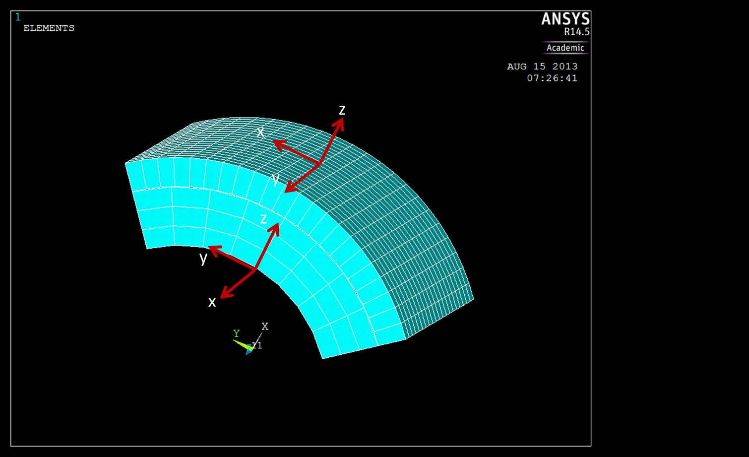
Hallo Leute, ich bin neu hier und habe mich angemeldet, da ich absolut nicht mehr weiter weiß und hoffe, dass mir jemand von euch helfen kann. Ich antworte zunächst einmal in diesem Thema, da hier ähnliche Probleme behandelt werden. Ich habe folgendes Problem: Wie in der angehängten Bilddatei zu sehen, habe ich 2 Viertelkreiszylinder modelliert. Der innere ist ein Faserverbundlaminat und der äußere besteht aus einem anderen orthotropen Material. Die Daten sind auch im beigefügten Skript aufgeführt.
Das Laminat modelliere mit SOLSH190 Elemente, da es layered ist. Das äußere orthotrope Material soll ein einfaches SOLID185 Element sein. Und hierbei besteht dann auch gleich ein Problem. Wie bekomme ich die Elemente so gedreht, dass sie entsprechend der beigefügten Bilddatei ausgerichtet sind?
Bei SOLSH190 funktioniert das gut mit VEORIENT. Bei SOLID185 weiß ich leider nicht, wie das mache. Ich habe auch versucht, SOLID185 ebenfalls als layered mit dann nur einer Schicht zu definieren. Dann hat es mit der richtigen Ausrichtung geklappt. Jedoch werden dann die Materialeigenschaften des äußeren orthotropen Materials nicht mehr berücksichtigt. Bei einer Temperaturbeaufschlagung wird dies deutlich. Setzt man die Wärmeausdehnungskoeffizienten des Laminats auf 0 und die des orthotropen Materials ungleich 0, dann passiert nichts. Beide Werkstoffe dehnen sich nicht aus. Setzt man jedoch die Wärmeausdehnungskoeffizienten des Laminats ungleich 0, dann wird dies für beide Werkstoffe übernommen. Woran liegt das? Kann mir jemand helfen? Das wäre mir eine riesige Hilfe, da ich absolut nicht mehr weiter komme!! Vielen Dank!!! und beste Grüße
David [Diese Nachricht wurde von Dave1987 am 15. Aug. 2013 editiert.] Eine Antwort auf diesen Beitrag verfassen (mit Zitat/Zitat des Beitrags) IP |
MESHPARTS
Mitglied
Beiträge: 411
Registriert: 08.03.2013 Meshparts Software (https://www.meshparts.de/products)
Ansys
SolidWorks
|
erstellt am: 15. Aug. 2013 14:07 <-- editieren / zitieren --> Unities abgeben: Nur für Jens.Friedrich
Hallo Jens, ist es nicht einfacher, wenn du die richtungsabhängigen Materialeigenschaften vertauscht? Wenn Anys die Elemente nach einem zylindrischen Koordinatensystem schon richtig dreht, dann müsste man bei dir nur die Achsnamen in der Materialdefinition vertauschen. Ansonsten, wenn es unbedingt mit deinen Achsnamen klappen soll, kann man mit APDL ein lokales Koordinatensystem für jedes einzelne Element mit der richtigen Ausrichtung definieren. Viele Grüße
Alex ------------------
MESHPARTS
Tuning Your Simulation
www.meshparts.de Eine Antwort auf diesen Beitrag verfassen (mit Zitat/Zitat des Beitrags) IP |
| Anzeige.:
Anzeige: (Infos zum Werbeplatz >>)
 |

 Foren auf CAD.de


 |
|